For definitions, general notes on methods of test and the complete series of methods of test for winding wires, see IEC 60851-1.
The equipment used shall have a precision better than 2 µm. If a micrometer, which contacts the
wire, is used, it shall be ensured that the measuring force is in the range as given in table 1 . The
diameter range of the spindle and the anvil is also given in table 1 .
1 Scope
This part of IEC 60851 specifies the following method of test:
Test 4: Dimensions.
For definitions, general notes on methods of test and the complete series of methods of test
for winding wires, see IEC 60851-1.
2 Normative references
The following referenced documents are indispensable for the application of this document.
For dated references, only the edition cited applies. For undated references, the latest edition
of the referenced document (including any amendments) applies.
IEC 60851-1, Winding wires – Test methods – Part 1: General
IEC 60851-5:2008, Winding wires – Test methods – Part 5: Electrical properties
3.1 Equipment
Round and rectangular wire
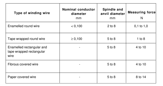
The equipment used shall have a precision better than 2 µm. If a micrometer, which contacts the
wire, is used, it shall be ensured that the measuring force is in the range as given in table 1 . The
diameter range of the spindle and the anvil is also given in table 1 .

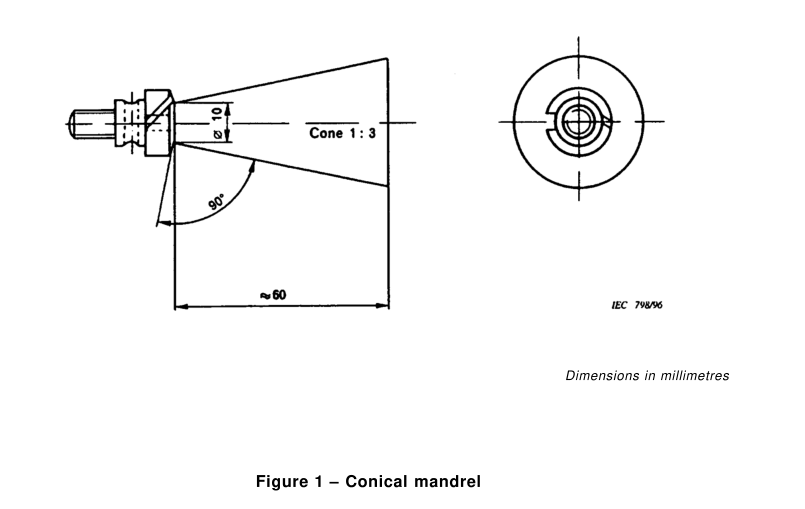
3.1.2 Bunched wire
The measurement shall be made with a polished conical mandrel having dimensions as shown in
figure 1 .
3.2 Procedure
3.2.1 Conductor dimension
3.2.1.1 Round wire
NOTE – See table 2.
3.2.1.1.1 Nominal conductor diameter over 0,063 mm and up to and
including 0,200 mm
From a straight piece of wire the insulation shall be removed at three places, 1 m apart, by any
method that does not damage the conductor. One measurement shall be made at these three
places.
The three single values shall be reported. The mean value represents the conductor diameter.
3.2.1.1.2 Nominal conductor diameter over 0,200 mm
From a straight piece of wire, the insulation shall be removed by any method that does not
damage the conductor. Three measurements of the bare conductor diameter shall be made at
points evenly distributed around the circumference of the conductor.
The three single values shall be reported. The mean value represents the conductor diameter.
Type of winding wire
Nominal conductor
diameter
mm
Spindle and
anvil diameter
mm
Measuring force
N
Enamelled round wire< 0,1 00 2 to 8 0,1 to 1 ,0
Tape wrapped round wire ≥ 0,1 00 5 to 8 1 to 8
Enamelled rectangular and – 5 to 8 4 to 1 0
tape wrapped rectangular
wire
Fibrous covered wire- 5 to 84 to 1 0
Paper covered wire – 5 to 8 8 to 1 4
3.2.1.2 Rectangular wire
The insulation shall be removed at the three places used for measurements in 3.2.5.2 by any
method that does not damage the conductor. At each place one measurement of the two
dimensions of the conductor shall be made.
The three single values shall be reported for each dimension of the conductor. The mean
represents the conductor width or the conductor thickness respectively.
3.2.2 Out-of-roundness of the conductor
Out-of-roundness is the maximum value of the difference between any two readings of the
conductor diameter at each cross-section. The measurement shall be made in accordance
with 3.2.1 .1 .
The out-of-roundness shall be reported.
3.2.3 Rounding of corners of rectangular wire
For the purpose of this test, a cross-section of the wire shall be prepared and then examined under
a sufficient magnification.
Three straight pieces of wire shall be cast in a suitable resinous compound, that will not affect the
insulation. After curing, the colour of the resinous compound shall contrast with the colour of the
insulation.
The specimen consisting of the three pieces of wire embedded in the cured resinous compound
shall be cut at right angles to the length of the wire pieces and the cross-section shall be carefully
ground and polished by suitable means. The polished surface shall be examined under a
magnification which allows a correct judgement of the rounding of corners.
It shall be reported how the arc merges into the flat surface of the conductor. Any sharp, rough and
projecting edges shall also be reported.
3.2.4 Increase in dimension due to the insulation
The increase in dimension due to the insulation is the difference between the overall dimension
and the conductor dimension.
3.2.4.1 Round wire
The measurement shall be made in accordance with 3.2.1 .1 and 3.2.5.1 . The difference between
the overall diameter and the conductor diameter shall be reported as increase in diameter.
3.2.4.2 Rectangular wire
The measurement shall be made in accordance with 3.2.1 .2 and 3.2.5.2. The difference between
the overall width and the conductor width shall be reported as the increase in width. The difference
between the overall thickness and the conductor thickness shall be reported as increase in
thickness.
3.2.5 Overall dimension
3.2.5.1 Round wire
3.2.5.1.1 Nominal diameter up to and including 0,200 mm
On a straight piece of wire, at three places 1 m apart, one measurement of the overall diameter
shall be made.
The three single values shall be reported. The mean value represents the overall diameter.
3.2.5.1.2 Nominal conductor diameter over 0,200 mm
On a straight piece of wire, at each of two places 1 m apart, three measurements of the overall
diameter shall be made at points evenly distributed around the circumference of the wire.
The six single values shall be reported. The mean value represents the overall diameter.
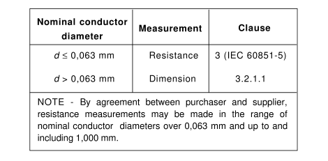
For determination of the conductor diameter as given in the relevant standards, the following
applies:
Table 2 – Determination of the conductor diameter
3.2.5.2 Rectangular wire
On a straight piece of wire at each of three places at least 1 00 mm apart, one measurement shall
be made of the two dimensions of the wire. Where the dimension of the specimen is greater than
the diameter of the micrometer spindle, measurements shall be made both at the centre of the
face of the specimen and over the edges. If these values differ, only the highest value shall be
noted.
The three single values shall be reported for each dimension of the wire. The mean values
represent the overall width or the overall thickness respectively.
3.2.5.3 Bunched wire
NOTE – The method indicated below gives useful values in practice, but not an accurate overall diameter.
The overall diameter is the width of a layer wound on a mandrel divided by the number of turns.
The bunched wire shall be wound closely on a mandrel according to figure 1 and under a tension
in newtons, which is 65 times the total nominal cross-section of the conductors in square
millimetres. The width of the layer shall be not less than 1 0 mm for bunched wires with overall
diameters up to and including 0,5 mm, and be not less than 20 mm for larger diameters and shall
be measured with a precision of 0,5 mm.
One measurement shall be made. The overall diameter rounded off to 0,01 mm shall be reported.
3.2.6 Increase in diameter due to the bonding layer of enamelled round wire
The increase in diameter due to the bonding layer is the difference of the overall diameter with and
without the bonding layer.
The overall diameter of the wire shall be measured according to 3.2.5.1 . After removal of the
bonding layer by means of a solvent or any other suitable agent or by any other method which
does not damage the underlying coating, the measurement shall be repeated. The difference of
the two mean values shall be reported as the increase in diameter due to the bonding layer.