
Ideally, the winding should be positioned parallel to the winding flange, meeting an orthogonality condition. It is necessary to adjust the winding width to the number of turns per layer of the winding. For non-circular shaped coil cross-sectional areas, it is preferable to locate the crossover area to the small side of the coil body, also called winding head. This is because the non-circular coils are being mounted on a sheet metal package or in a circular arrangement. The coils should be rather small, in order to avoid a contact with the neighboring coil or the sheet metal package. For Orthocyclic round coils, three winding geometries can be defined:
1. Equal number of turns per layer
2. Unequal number of turns per layer, starting with shortened layer

3. Unequal number of turns per layer, starting with longer layer
The choice of the winding structure to be used basically depends on the design of the coil or the coil body. Among others, the available space conditions for winding width and winding height must be considered. Moreover, it is possible to influence the location and the end of the last winding by selecting a clever winding pattern. The winding height of an Orthocyclic coil winding results from the following equation:
h = [1+(n-1) – sin 60° – d
h – Winding height
n – Number of layers
d – max. wire gauge above the varnish (CuL)
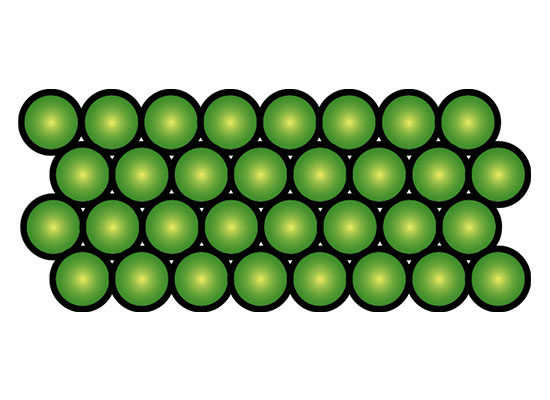
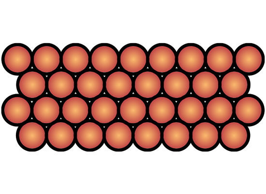
An Orthocyclically wound coil with at least 300° of the circumference of winding layers has the tightest circle package of the wire cross-sections. This winding method reaches the highest fill factor and is the best way to fill the available winding cross-section with round wires. Square coils are seen as Orthocyclically wound when the winding and layer jump occur only on one of the sides of the winding cross-section.
In theory, a geometric fill factor of 0.91 will be reached. In practice, however, the value cannot be reached because there exists a winding jump and layer jump area and the wire insulation is not taken into account.